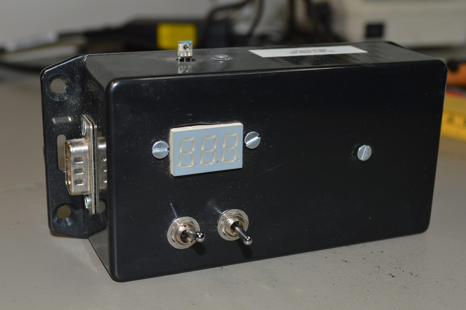
Measures light intensity and shows the value on a LED display, if value passes over/under the set point the output is enabled. Uses the AVR ATmega8 microcontroller.
Table of contents
Details
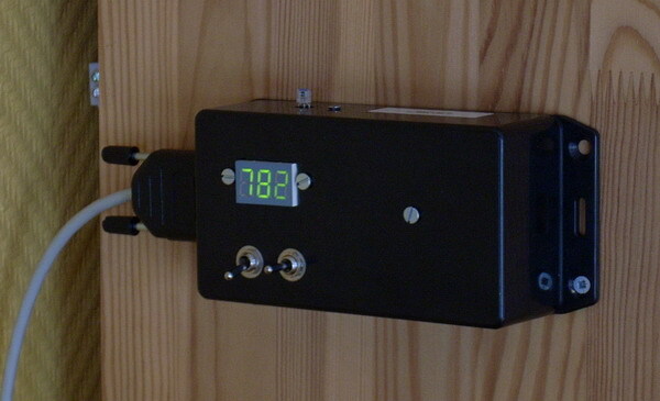
This module measures light intensity and shows it on a scale from 0 to 782 on the LED display. By multiplying that value with 5, and then divide by 127 you get the light intensity in µW/cm2. If the light intensity rises over or falls below (configurable) the set point; the output activates, with a hysteresis of +-25. The module has two outputs; a constant and a pulse. The constant output can be used to drive e.g. a relay, while the pulse can communicate with other equipment. Powered by: 9-24V.
Set points
The set point is adjusted using the (on)-off-(on) switches, when adjusting; the display shows this instead of the real value. It is stored in EEPROM making it non-volatile, meaning that it is not lost if the module is without power.
Video
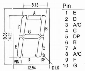
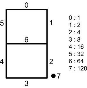
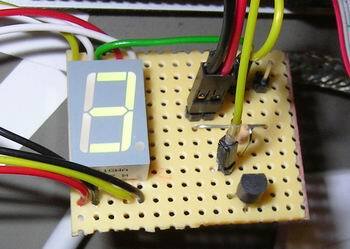
LED-Display
In reality only one digit is shown at any given time, but by cycling through them in high speed the human eye sees three stable digits.
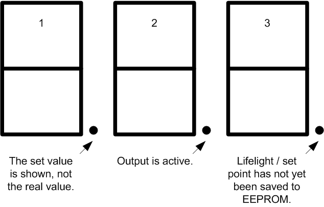
When DP x is lit:
- The set value is shown, not the real value.
- Output is active.
- Set point has not yet been saved to EEPROM.
I/O
Inputs
- PC.0 Light sensor, analog value
- PC.1 Set point up
- PC.2 Set point down
- PC.3 Active when over or under set point
Calculations
Light intensity
ADC × 5   µW
------- ≈ --- ± 0.039
  127     cm²
Outputs
- PB.0 LED-display digit 1
- PB.1 LED-display digit 2
- PB.2 LED-display digit 3
- PB.3 Output constant
- PB.4 Output pulse
LED-Display I/O
- PortD.0 LED-display A
- PortD.1 LED-display B
- PortD.2 LED-display C
- PortD.3 LED-display D
- PortD.4 LED-display E
- PortD.5 LED-display F
- PortD.6 LED-display G
- PortD.7 LED-display DP
D-Sub 9-pin
- 9-15V +
- GND
- Output constant
- Output pulse
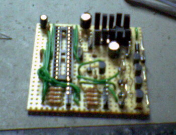
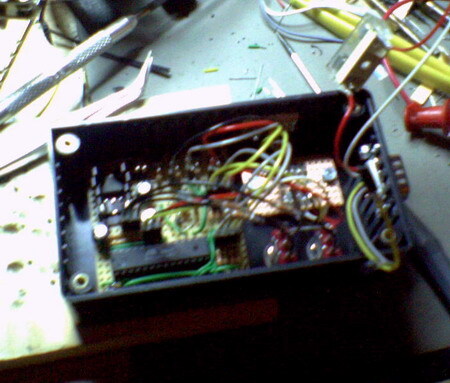
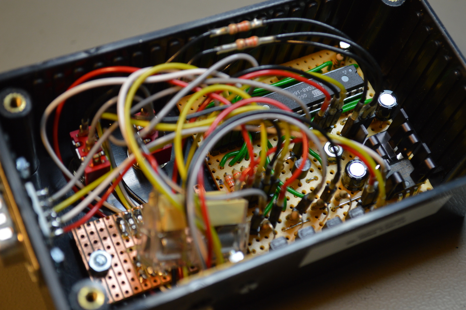
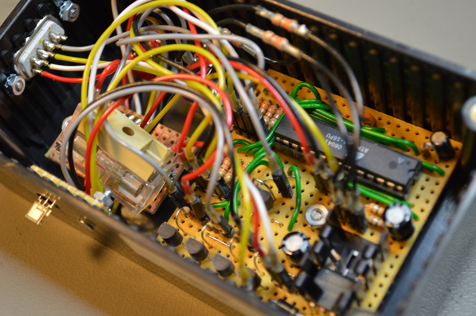
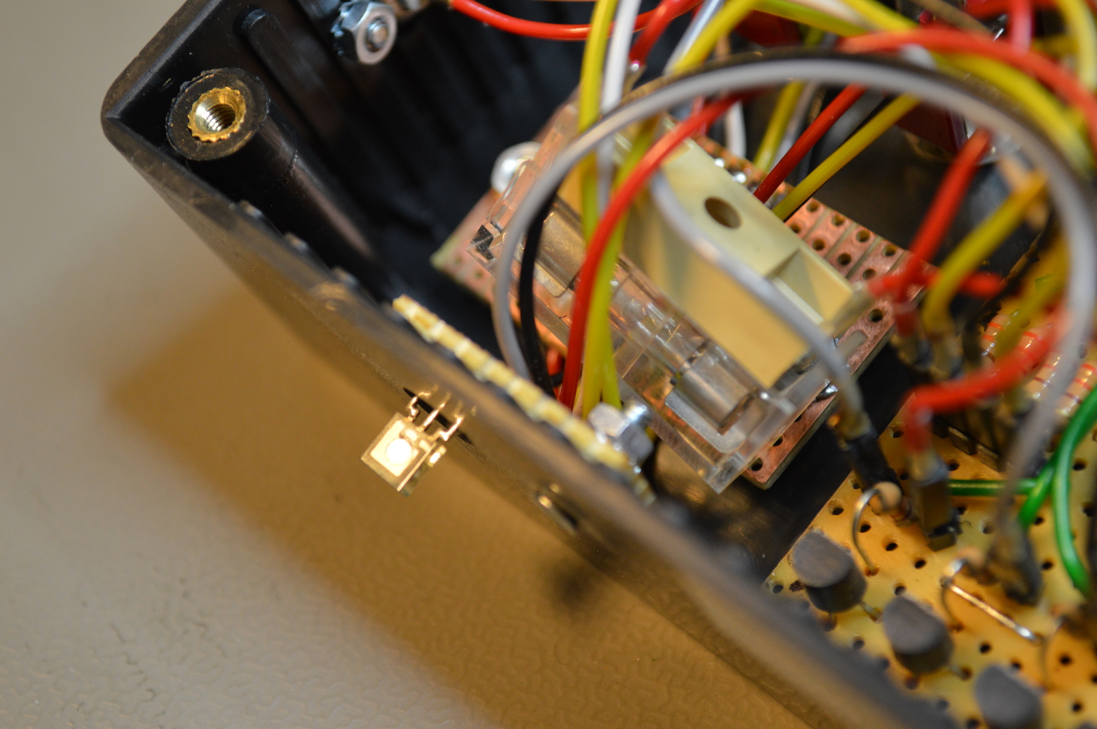
Photos
Source code
- Bascom-AVR source is available in a git repository:
- https://github.com/thomasjsn/AVR-Light-sensor
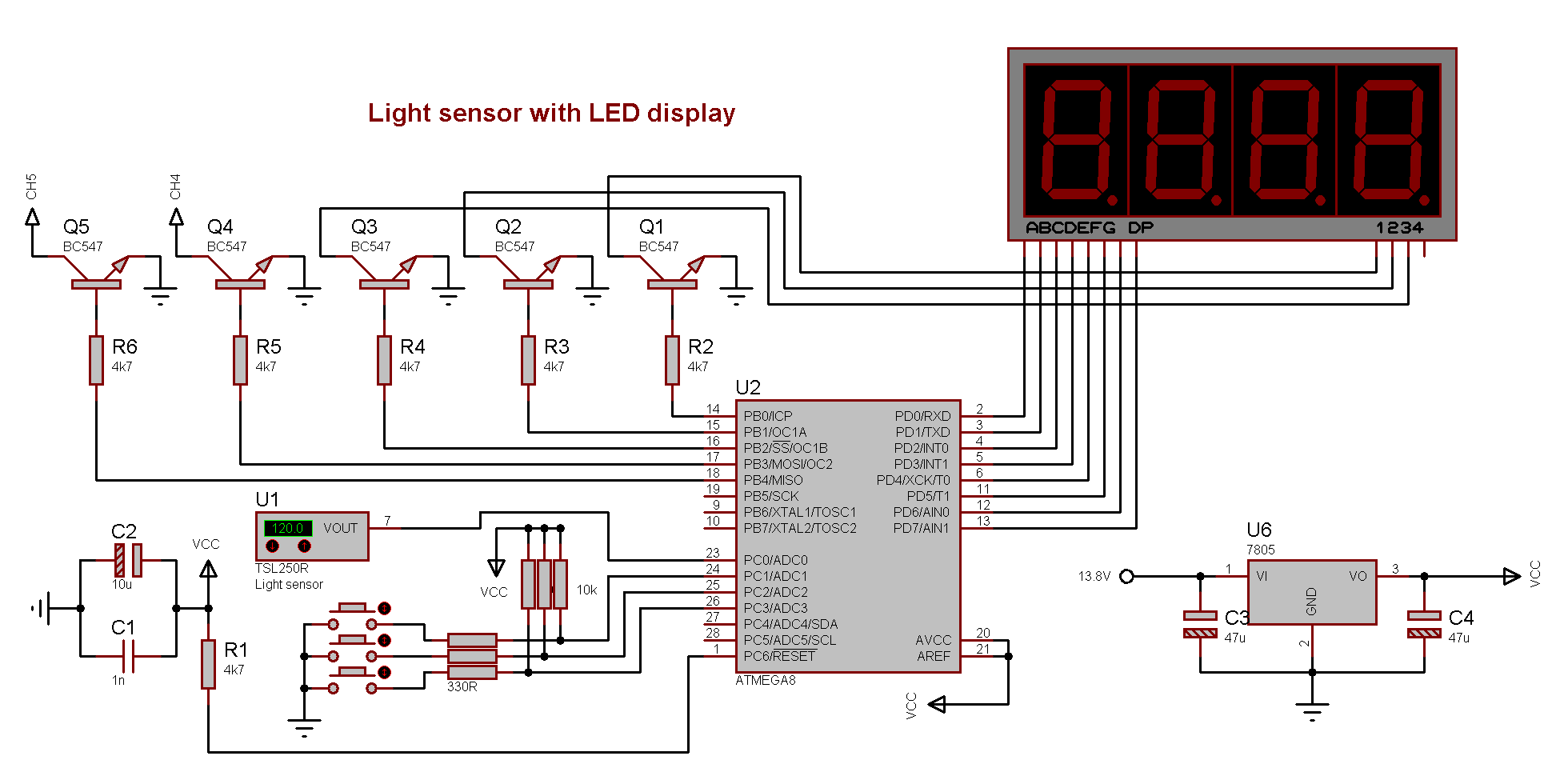
Schematic drawing
Parts list
- 1 × AVR ATmega8-16PU, DIL-28, 16 MHz, 23 I/Os
- 1 × Capacitor, aluminium electrolytic, 10 µF, 25V
- 2 × Capacitor, aluminium electrolytic, 47 µF, 25V
- 1 × Capacitor, ceramic, 1 nF, 100V
- 2 m Control cable, 4-cores, 0.25mm2, 250 V, Ø 4.6mm
- 1 × D-sub soldering cups, 9 pin male
- 1 × DIL socket, 28-pin, 7.62mm
- 1 × Diode, rectifier, 1 A, 400V, 1N4004
- 1 × Enclosure, plastic (1591 FL), 120x65x40mm, flange
- 1 × Fuse 5x20 mm, 400 mA, fast-acting
- 1 × Fuse holder, open, PCB, 5x20mm
- 1 × Fuse holder, open, PCB, Protective cover
- 1 × Heatsink, 27.3K/W, 19mm, attachable, TO220
- 1 × LED display, 3x7-segment, 9.2mm, Green
- 1 × Light-to-voltage sensor, TSL 250R, 127mV / (μW/cm2)
- 32 cm2 PCB, stripboard, 100x160mm, 160cm2
- 11 × Resistor, carbon film, 0.25W, 330 Ω, 5%
- 6 × Resistor, carbon film, 0.25W, 4.7 kΩ, 5%
- 3 × Resistor, carbon film, 0.25W, 10 kΩ, 5%
- 3 × Spacer, round unthreaded, 3mm, Ø6mm, Delrin
- 22 × Straight pin header, female, Single row, 2.54mm
- 22 × Straight pin header, male, Single row, 2.54mm
- 1 × Switch, toggle, 1-pole, micro, (on)-off-(on)
- 1 × Switch, toggle, 1-pole, micro, on-on
- 5 × Transistor, NPN, 100 mA, 45V, 0.5W, BC547B
- 1 × Voltage regulator +5V, 2 A, L78S05CV
Last commit 2021-08-06, with message: replace some youtube videos