This post is part of the Rack Box Project series.
Reads temperature and controls a fan using a PWM output, fan and alarm set point can be adjusted and is shown on a LCD. Uses an AVR ATmega8 microcontroller.
Table of contents
Details
The module uses an LM35 sensor for measuring the temperature, it is a pre-calibrated IC with output voltage linearly-proportional to the Centigrade temperature. This is read directly by the internal AVR ADC, and turned into actual degrees with a simple calculation.
The fan is powered by an PWM output, giving it variable speed. Set points for the fan and alarm can be adjusted and is saved to EEPROM.
When the temperature reaches the set point; the fan will start on speed 1. After 30 seconds the speed is increased to level 2, unless the temperature has dropped below the set point. If the temperature rises above the set point speed is set to level 3, which is the maximum.
The alarm is triggered if the temperature is equal to the alarm set point for more than 30 seconds. It is possible to override the fan with the override switch, or with an external signal. When overridden the fan speed is increased by 2, meaning if 0 then 2, or if 1 or 2 then 3.
Set points
Two values are stored in EEPROM; fan and alarm set point. These are non-volatile, meaning that they are not lost if the module is without power.
Set points are saved to the EEPROM about five minutes after they have been changed, to avoid unnecessary writes. When values are changed but not yet saved; a E is displayed in the right corner if the LCD. The set points is adjusted using the (on)-off-(on) switches, one degree at the time.
Original purpose
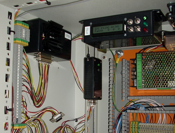
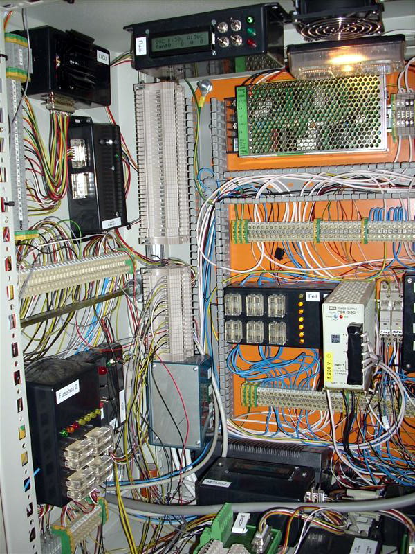
The controller was originally built for the rack box project:
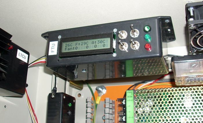
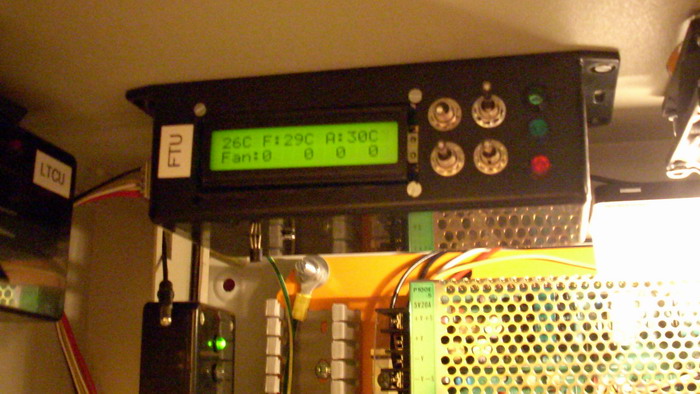
FTU regulates the temperature in the Rack box. The module is equipped with a LM35 temperature sensor, installed in the top of the Rack box were it’s warmest. A 80x80 mm fan is also mounted at the top of the box.
The air intake is at the bottom and sucks air from outside the entire closet. This gives good air circulation in the Rack box. The fan is controlled using PWM, giving the fan variable speed. It’s divided into three levels: 1: 1/3, 2: 2/3, 3: full.
Videos
The fan controller can be seen at 0:45
- Starting the fan using the override switch
- Adjusting fan set temp
- Setting alarm set point below current temperature
- After 30 seconds the temperature alarm is triggered
- Setting the alarm set point back to its original value
I/O
Inputs
- PB3 Fan set temp +
- PB4 Fan set temp -
- PB6 Alarm set temp +
- PB7 Alarm set temp -
- PB5 Override fan switch
- PC0 Temperature (Analog)
Calculations
Temperature
ADC × 5
------- ≈ °C ± 0.5
  10
Outputs
- PD0 LCD1
- PD1 LCD2
- PD2 LCD3
- PD3 LCD4
- PD6 LCD5
- PD7 LCD6
- PB0 Life-signal (to Module stability monitoring unit 2)
- PB1 Fan
- PB2 Temp alarm (to Signal and lights controlling unit)
D-Sub 9-pin
- 0V
- +5V
- Life-signal
- Fan
- Temp alarm
- LCD background light switch
- Override fan switch
Front panel
Switches
- (on)-off-(on), fan temp +/-
- (on)-off-(on), alarm temp +/-
- on-off, override fan
- on-off, background light LCD display
LEDs
- Green, Life-signal
- Green with lens, fan active
- Red with lens, temp alarm
LCD Display

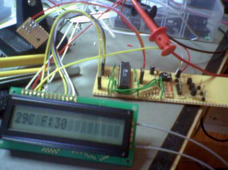
Below are the different messages and statuses shown on the LCD display.
1234567890123456
25C F:30C A:30C*
Fan & Temp Unit!
SW v.2.0
JensenCorp.no
System start =)
Source code
- Bascom-AVR source is available in a git repository:
- https://github.com/thomasjsn/AVR-Fan-and-temperature-controller
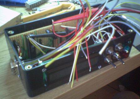
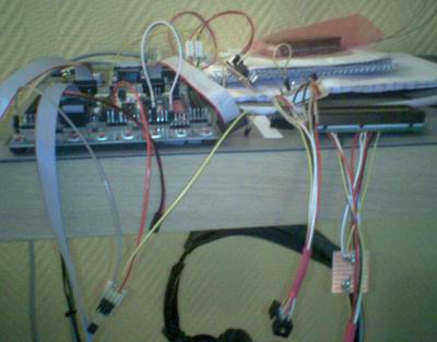
Photos


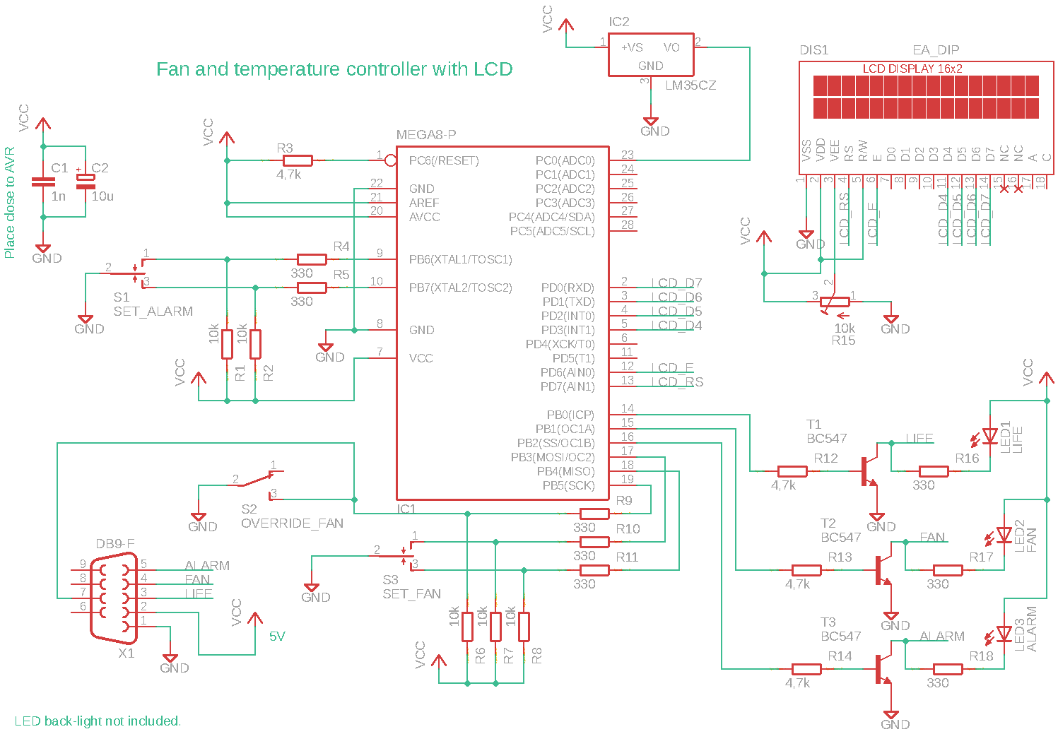
Schematic drawing
Parts used
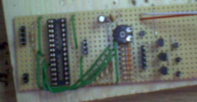
- 1 × AVR ATmega8-16PU, DIL-28, 16 MHz, 23 I/Os
- 1 × Capacitor, aluminium electrolytic, 10 µF, 25V
- 1 × Capacitor, ceramic, 1 nF, 100V
- 1 × D-sub soldering cups, 9 pin female
- 1 × DIL socket, 28-pin, 7.62mm
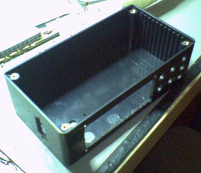
- 1 × Enclosure, plastic (1591 FL), 150x80x50mm, flange
- 1 × LCD display, dot matrix, 16x2, LED green
- 1 × LED 5mm clear, Green, 2.1V, 20mA, 385mcd, 6°
- 1 × LED 5mm clear, Red, 2.0V, 20mA, 140mcd, 6°
- 1 × LED 5mm coloured clear, Green, 2.1V, 20mA, 30mcd, 10°
- 1 × LED holder 5mm, RTC51, black plastic
- 1 × LED lens 5mm, CLF 280, Green
- 1 × LED lens 5mm, CLF 280, Red
- 32 cm2 PCB, stripboard, 100x160mm, 160cm2
- 8 × Resistor, carbon film, 0.25W, 330 Ω, 5%
- 4 × Resistor, carbon film, 0.25W, 4.7 kΩ, 5%
- 5 × Resistor, carbon film, 0.25W, 10 kΩ, 5%
- 18 × Straight pin header, female, Single row, 2.54mm
- 18 × Straight pin header, male, Single row, 2.54mm
- 2 × Switch, toggle, 1-pole, micro, (on)-off-(on)
- 2 × Switch, toggle, 1-pole, micro, on-on
- 1 × Temperature sensor LM35DZ, 0 to +100 °C, +-0,6 °C
- 3 × Transistor, NPN, 100 mA, 45V, 0.5W, BC547B
- 1 × Trimmer, carbon, 10 kΩ, horizontal
Last commit 2024-04-05, with message: Tag cleanup.
Rack Box Project series
- Parallel port I/O module
- Power supply and fuse monitoring module, AVR
- Monitored fuse box, 6 channels
- Stack lights and horn controller — with AVR
- Mute and light controller for the Rack box — AVR module
- Monitored fuse box, 4 channels
- Module heartbeat monitor, 6 inputs — AVR
- Controller for lights and relays — AVR driven
- Emergency power off controller — controlled by 555 timers
- Fan controller with LCD — AVR powered
- Sound alarm control unit — AVR module
- Multiplexer output extender
- Multi-purpose AVR module
- Electric heater and timer controller — AVR
- Module heartbeat monitor, 15 inputs — LCD and AVR
- Serial port I/O module with 11 inputs — AVR
- Serial port I/O module with 9 in and outputs — AVR
- Serial interface for emergency power off — AVR
- Status panel for the Rack box project
- Intruder alarm system controller — AVR
- Serial port I/O module with 15 inputs — AVR
- Serial interface module, with analog and digital I/O — AVR
- The rack box project — an overview